 |
12th Doctor's 2nd Sonic |
Here's a load of info about how I made a replica of this sonic.Features...
* 3D printed parts (not my original design, but modded)
* sanded for 4.5 billion years and painted
* contains an Arduino Pro Mini processor
  + FLORA 9dof Accelerometer / Gyro / compass board
* Five RGB 'NeoPixel' LEDs on a tiny custom PCB (Red Mode - yay!)
* Little amplifier to drive an 8-ohm speaker on 2nd PCB
  (also includes 3v regulator for the Accelerometer)
* Custom software to handle effects and sound generation
  + Light effects with full RGB and nice fading
  + Sonic sounds generated by Direct Digital Syntheses (ooh!)
  + 'wav' audio playback for other sonic sounds
  + Synthesised playing of Dr. Who theme melody
  + Uses Accelerometer to detect gestures for effect changes
    also alters sonic sound effects according to angle
  + Magnetometer triggers sound/light effects (TODO)
  + Compass mode: pip... pip... pipipipip, that's North! (TODO)
  + Ooo-Eee-ooo mode: wave it for theramin-like music (hmm, maybe)
Mk I. 19th Dec 2017 TonyWilk "mail at tonywilk dot co dot uk" |
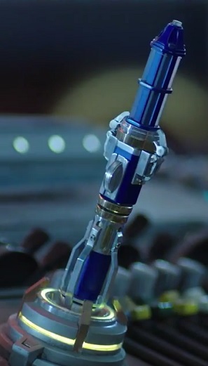 No, this one isn't mine |
Building a Sonic
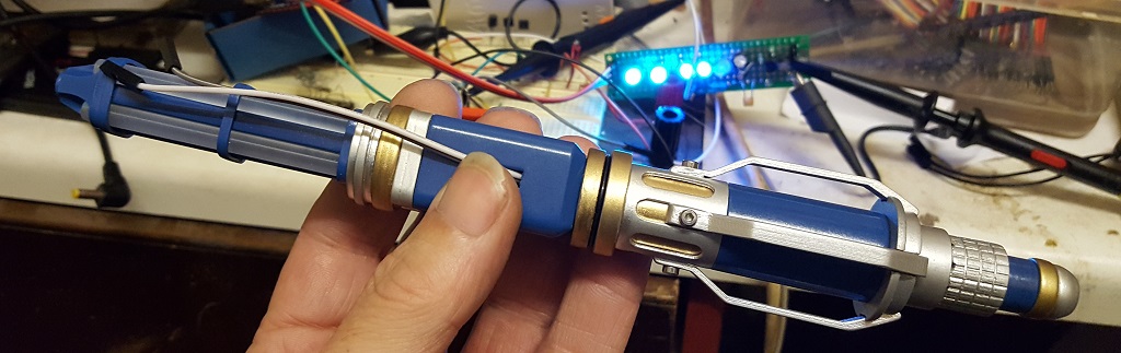
my sonic in dev. - yep, that really is 3D printed :)
Some of the elements of the build might be of interest for other projects:
The 3D printer model
Audio amplifier design and PCB
NeoPixel LED PCB
Arduino software
- sound generation (while driving NeoPixels !!)
- Accelerometer routines
- etc.
General Notes
- Had to modify the original 3d model to get the electronics to fit.
- it is still a really tight fit! - Used an Arduino Nano Pro ('Pro mini')- that's a version of the Nano without the USB on board
- that means you have to use a USB interface to program the device.
- The code is written for this hardware only 'cos it used interrupts and stuff
- Made a custom pcb for a single-transistor speaker amplifier and a 3v regulator for the 9dof
- Uses a tiny 'FLORA 9-DOF' accelerometer board
- The FLORA sensor I used was nice and small but needed 3V
- looking today (May 2022) you could use this: Adafruit LSM9DS0 which uses the same device but can run on 5v
- updated March 2026: Adafruit LSM9DS1 new code below - I also made a tiny PCB to mount the RGB LEDs - tho you could hard-wire them
- If I built it again I'd resin-print all the parts and make it slightly larger (by say 5%)
Build Pictures
There's a bunch of build pictures on this page3d Print
Original 3D design at Thingiverse:12th Doctor's Sonic Screwdriver by Shipbrook
Modifications by me:
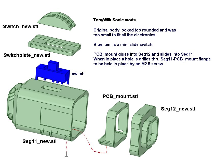
STL files:
Arduino code
I'm afraid the code is none too tidy - I messed about with it until it all worked and never got around to cleaning it all up.The 5 RGB NeoPixels are driven from bit 4 of PORTD 'D4' (see Arduino_Pro_Mini_schematic.pdf)
PWM audio is output on pin 9 (D5), samples are output by an interrupt routine which has some complications !
(there are some notes in the code)
I hacked about an interface for the LSM9DS0 sensor accel.h and accel.cpp which are in the TW_LSM9DS0 subdirectory.
New version (March 2026) uses the LSM9DS1 sensor
I think I put this directory in Arduino/libraries for it to compile with the .ino sketch.
There's commented-out code at the bottom of sonic12.ino that I used to generate the colour palette used for driving the LEDS.
The code wrote this page: colour_palette.html ahowing the indexes and RGB values.
Note: I've retrieved all this lot from my backup server so I hope it's all complete
(it was developed on a now long-dead Windows XP machine I seem to remember)
If you think there's anything missing, drop me a line at: mail at tonywilk dot co dot uk
The whole code is in this sonic12.zip file
*NEW VERSION* is in this sonic_24-3-2026.zip file
There are some additional notes in Documents/Readme.pdf
PCB designs
Audio amp + regulator schematic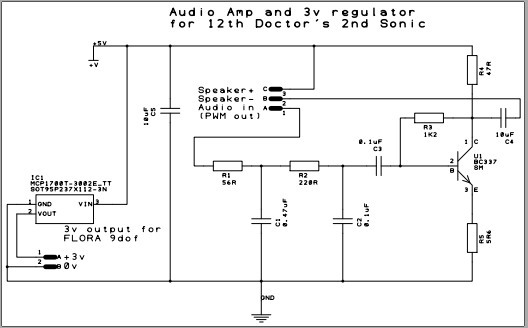
The "sonicLEDS" pcb was a right pain, probably easier just to hard-wire them in place
and you would save space without the PCB
The end.
Back to The War Doctor